
A SMALL UPDATE
I’ve decided to add a small update to the last chapter. I would like to add a little explanation about where the lines in the project come from and how they’re scaled. I’ve also improved the way a line’s data is inputted into the project, making their creation more automatic, and thus much easier. The scene being used for collision is also a little more interesting, using angled lines to denote a sort of path through a forest leading to a little clearing on the right side. A new source code folder will be available for download at the end of this short chapter that contains all of this.
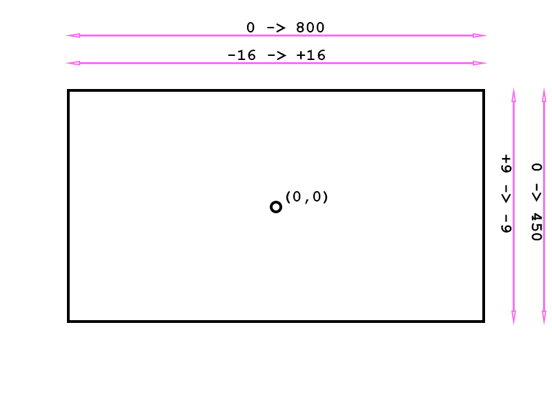
The original book I learned this from which is shown in the previous chapter used a horizontal scale of 800 units and a vertical scale of 450 units, and began from the origin at the top left corner of the page.
In this project up to now we’ve been using a rectangle that is only 2 units across and thus lines on a scale of hundreds of units would have dwarfed the rectangle. So I kept the rectangle in our project at 2 units square in size and simply scaled the lines down by a factor of 25. The rectangle used for the character tile in the textbook was 50 units squared rather than 2, hence where the factor of 25 comes from.
I’ve also put the origin right at the center of the scene so anything left of that will be negative, and anything right of it will be positive:
That might make some of the data make more sense in the header file that holds it all. Namely “Scene Data.h” header file in the Shared Headers folder. If you’ve looked through the last chapter’s source code (chapter 2a) you’ll have seen each line is declared in that file starting with a center, then a start point, an end point and finally a normal. Nothing was computed automatically, it all had to be computed offline manually. It involved a lot of trigonometry and was way too intensive to be realistic, despite my initial impressions.
The project has been updated now, so that all you need to enter is a start point and an end point. The project caters for rectangle line collision even when the rectangle is approaching the line from behind its face normal. A small bit of code I added to one of the collision detection functions makes this possible. However I still prefer the direction of normals to make sense given the scene data.
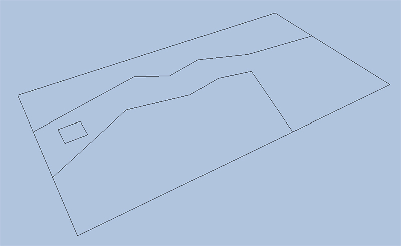
In short if you declare a line starting and ending from left to right, the normal will point in the downwards direction. If you declare one from right to left it will point in the upwards direction. For the new scene the uppermost lines are all declared left to right. For the lowermost lines only one is declared that way. The rest are declared from right to left:

And from a slanted view:
We’ll show a small snippet of the “Scene Data.h” file here. Note that I have defined data in this header file. At the moment I have my project setup so it is not accessed multiple times by different .cpp files so it isn’t causing a problem. I may change this though, as essentially it’s bad practice. This can lead to a multiple definition failure when attempting to compile. I’m unsure if I can just forward declare an std::array and then fill out its data in a .cpp file though. I suspect I probably can’t. I may have to make a small class for this in future versions of the project and make a header and .cpp file combination shared across projects.
The reason why this is a concern is because both the Geometry library and Render library both access the “Scene Data.h” file to create their data, albeit for different reasons. The file itself is stored in one place, and there is only one copy. When you make changes to the “Scene Data.h” file you must re-compile both the Geometry & Render library, or they won’t be using the same data. For now it’s working, but I suspect this will need a re-work in future versions of the project. As promised, here is the snippet from the “Scene Data.h” file:
std::array<float[3], 28> gScene1_Lines =
{
    // border1 (top border) - start, end
    -16.0f, 0.0f, 9.0f,
    16.0f, 0.0f, 9.0f,

    // border2 (bottom border) - start, end
    16.0f, 0.0f, -9.0f,
    -16.0f, 0.0f, -9.0f,

    // border3 (left border) - start, end
    -16.0f, 0.0f, -9.0f,
    -16.0f, 0.0f, 9.0f,

    // border4 (right border) -start, end
    16.0f, 0.0f, 9.0f,
    16.0f, 0.0f, -9.0f,

    // line1 (forest path 1) - start, end
    -16.0f, 0.0f, 3.0f,
    -5.2f, 0.0f, 5.8f,
That mostly concludes this little update. If for whatever reason you wish to see the line normals printed to the screen I have left a little commented out section of code in the Geometry Handler library’s LineShape class. Specifically LineShape’s member function CreateLineData(). If you uncomment this out, then every time a line is made this will show the x, y and z co-ordinates of the face normal for that line. Note that y is always zero, as collision detection takes place in the x-z plane only in this project.
When we want to finally add textured and interesting geometry to our scene we will just draw it within the bounding boxes marked out by our lines. This geometry will have y components too (or it would be flat), but it isn’t responsible for collision detection.
If you’d like to try this updated version of the project please download the source code from below (and as always – run a virus checker just in case!). Thank you for reading.
